Shear and Moment Diagrams |

|

|
Shear and Moment Diagrams |
|
|
Shear and Moment Diagrams
These diagrams display applied and resisting moments and shears plotted along the height of the stem.
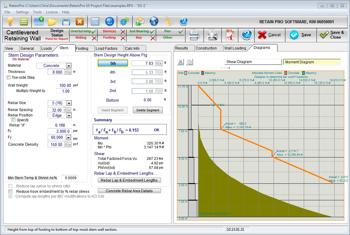
Each change in section (material, thickness, or reinforcing) is marked.
For concrete stem sections, the applied moments and shears are factored, and resisting moments and shears are design strengths based upon LRFD design.
For masonry stem sections designed according to LRFD, the applied moments and shears are factored, and resisting moments and shears are design strengths. For masonry stem sections designed according to ASD, the applied moments and shears are service-level loads, and resisting moments and shears are allowable strengths.
The moment resisting line is usually sloped to reflect the variation in resisting capacity with reduced remaining rebar development length.
These curves will be useful for visualizing and determining cutoff points for reinforcing, and general viewing of the stem adequacy.
This feature not available for gravity or segmental walls.