Soldier Pile Retaining Wall |

|

|
Soldier Pile Retaining Wall |
|
|
Soldier Pile Retaining Wall
Soldier pile retaining walls, also called soldier beam walls, are generally used at construction sites for temporary shoring. Steel piles are driven into the ground, or placed in drilled holes filled with lean concrete, at a spacing such that lagging can be placed between the piles, and the excavation can proceed down to the level of the finished grade on the low side. The stability of a soldier pile retaining wall depends upon the active earth pressure being resisted by passive pressure on the embedded section of the pile. Pile spacing is typically 6 – 10 feet on center.
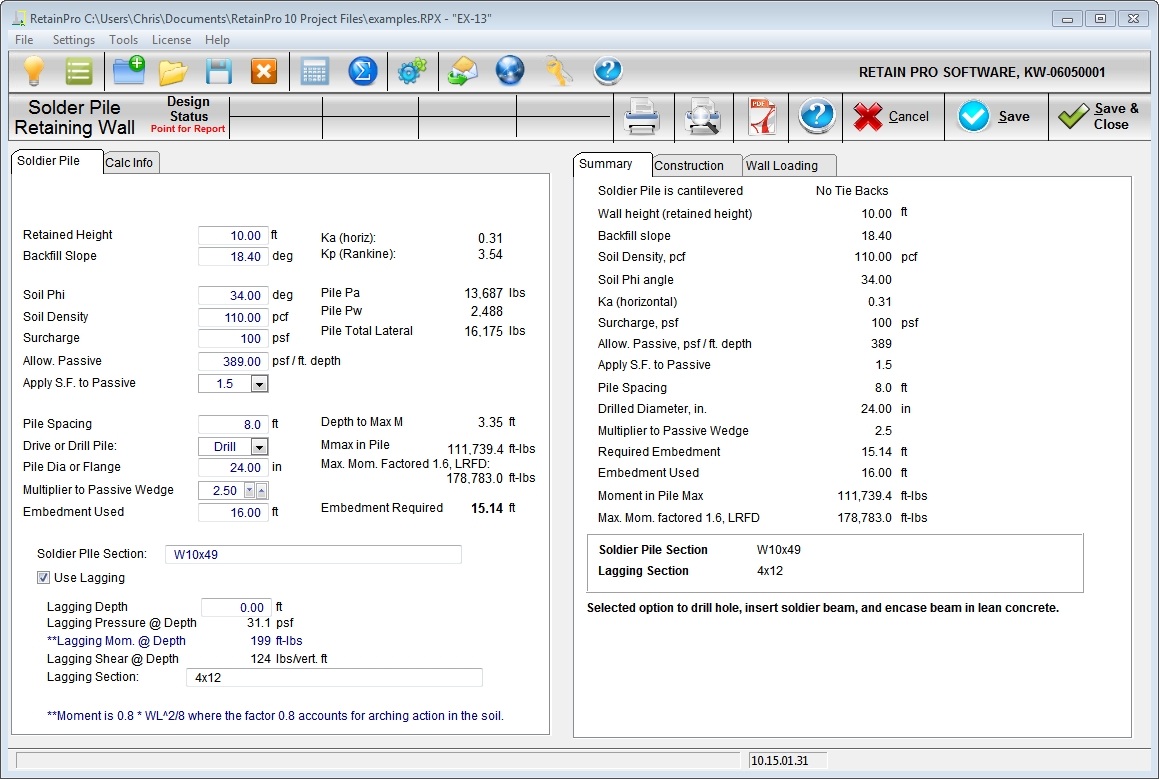
This program is currently only applicable to cantilevered soldier piles.
| Use Lagging: | Check this box if lagging is to be considered between piles. |
| Retained Height, ft: | Distance between the final excavated grade and the retained height at the top grade. |
| Backfill Slope, degrees: | Slope of the backfill measured in degrees from horizontal. |
| Soil Phi, degrees: | Angle of internal friction of the retained material, usually obtained from the geotechnical engineer. |
| Soil Density, pcf: | Density of the retained soil, usually 100 to 130 pcf. |
| Surcharge, psf: | Surcharge on upper grade such as for equipment, materials, or contingencies. |
| Allowable Passive, psf/ft: | Allowable passive pressure in pcf, usually (1/Ka)*(soil density). |
| Apply S.F. to Passive: | Safety factor that will be applied to the above allowable passive pressure, typically 1.5. |
| Pile Spacing, ft: | Center to center spacing of piles, typically 6 ft to 10 ft controlled by retained height pressure on wood lagging. |
| Drive or Drill Pile: | Select whether the steel pile is driven into the soil or placed into a drilled hole and encased in lean concrete. |
| Pile Diameter or Flange, in: | If the pile is driven, enter the flange width. If the pile is set in lean concrete in a drilled hole, enter the hole diameter. |
| Multiplier to passive wedge: | Multiplier from 1.0 to 3.0 to be applied to the pile flange width or drilled hole diameter due to wedging action and is usually provided by the geotechnical engineer. |
| Embedment used, ft: | Actual embedment, usually rounded from the required embedment reported below. |
| Soldier Pile Section: | Desired steel section, such as W10x49. The program does not actually perform Code checking on the selected steel section, but it does report values that will assist in performing that check separately. |
| Ka (horiz): | Computed automatically using the Rankine equation. |
| Kp (Rankine): | Calculated automatically and is 1/Ka as calculated above for a backfill slope of zero. |
| Pile Pa, lbs: | Total lateral force due to earth pressure. |
| Pile Pw, lbs: | Total lateral force due to surcharge if applicable. |
| Pile Total lateral, lbs: | Sum of Pa + Pw |
| Depth to Max M, ft: | Distance below lower grade to point of maximum moment in the pile. |
| Mmax in Pile, ft-lbs: | Maximum moment in the pile for which the steel pile is designed. |
| Max. Mom. Factored by 1.6 for LRFD design: | Mmax in Pile multiplied by 1.6. It is provided for convenience in checking the steel pile section for adequacy. |
| Embedment Required, ft: | Required pile embedment based upon allowable passive pressure, the specified safety factor and the applied active pressure. |
| Lagging Depth, ft: | Depth below grade at which lagging pressure is to be calculated based on the active soil pressure. |
| Lagging Pressure @ Depth, psf: | Pressure used in the design of horizontal wood lagging between piles. |
| Lagging Moment @ Depth, ft-lbs: | Moment computed assuming arching action and using moment = wl2/10. |
| Lagging Shear @ Depth, lb/vertical ft: | Shear computed using wl/2 where w is the Lagging Pressure @ Depth determined above. |
| Lagging selection: | Wood lagging selection, such as 4 in x 12 in. No design is performed based on this entry, but it is printed in the calculation report for reference. |