Stem Tab for Cantilevered Retaining Wall |

|

|
Stem Tab for Cantilevered Retaining Wall |
|
|
Stem Tab for Cantilevered Retaining Wall
When a Cantilevered Retaining Wall is defined, the Stem tab will appear as shown below:
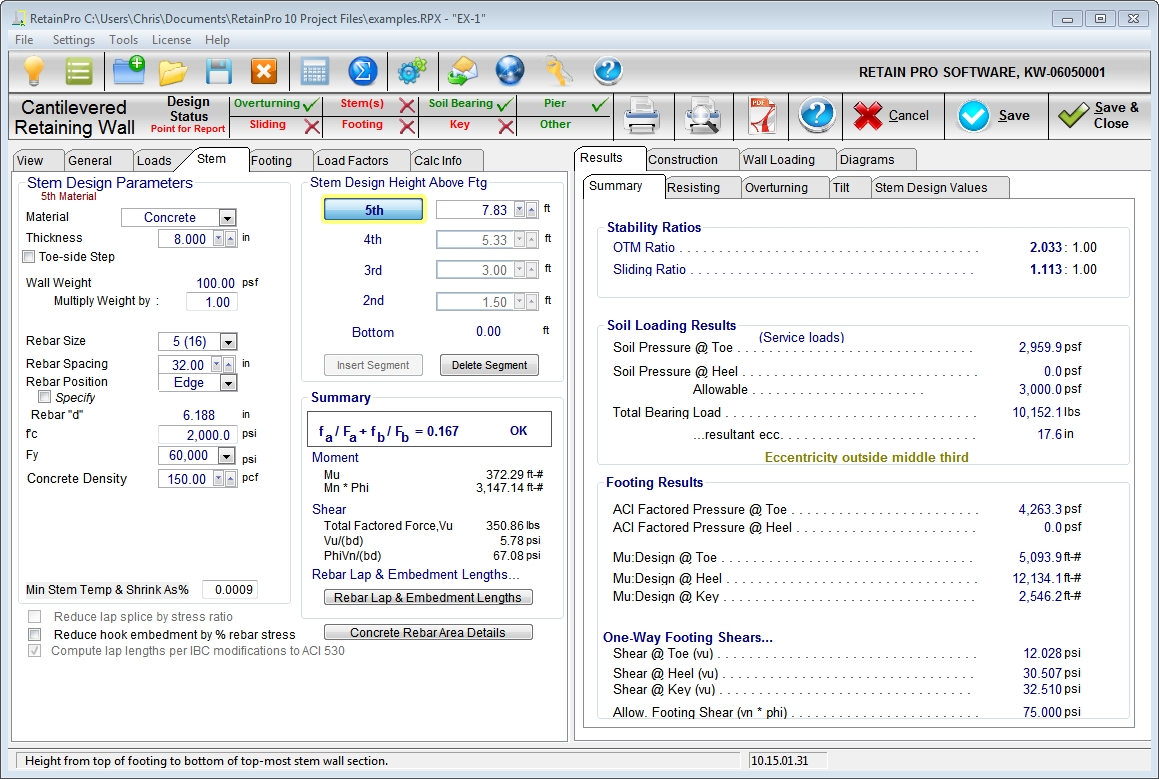
Stem Design Parameters
| Material: | Use the drop-down list box to select Masonry, Concrete, Fence, or None. Fence is only allowed on top of the wall, higher than the Retained Height, and is considered weightless. Use None to disable the stem section. |
| Thickness: | Use the spinners to set the thickness of Concrete wall segments. Use the drop-down list box to set the thickness of Masonry wall segments. For segments defined as "Fence" the thickness input is unavailable. |
| Wall Weight: | This displayed value is based upon wall data within the program. A multiplier input field is provided if it becomes necessary to adjust the data. See Appendix C for masonry wall weights. |
| Design Method: | When a masonry stem section is chosen, this allows a choice of ASD or LRFD (Allowable Stress Design or Load and Resistance Factor Design). When the latter is selected the input notations change (e.g. fs to fy) and all calculations are based upon LRFD. |
| Rebar Size: | Make your selection from the drop-down list box for bar sizes #3 to #10. “Soft Metric” sizes will be displayed in parentheses. |
| Rebar Spacing: | Use the spinners to set the rebar spacing in Concrete wall segments. Use the drop-down list box to set the rebar spacing in Masonry wall segments. For segments defined as "Fence" the rebar spacing input is unavailable. |
| Rebar Position: | Chose between Center or Edge. If Center is chosen, the rebar d distance will be 1/2 the actual wall thickness. If Edge is chosen the rebar will be located at the heel side of the stem as defined below. |
| For masonry wall segments, the program contains a table of the appropriate "d" values to use for various block sizes and center/edge locations, as shown in the table below. |
Default Values of Rebar Position for Masonry Wall Segments
Thickness |
|
Rebar Depth (in) |
|
|
Center |
|
Edge |
6" |
2.75" |
|
2.75" |
8" |
3.75" |
|
5.25" |
10" |
4.75" |
|
7.25" |
12" |
5.75" |
|
9.0" |
14" |
6.75" |
|
11.0" |
16" |
7.75" |
|
13.0" |
For concrete wall segments, the "edge" rebar depth is always stem thickness less 1.5" for #5 and smaller bars (stem thickness less 2" for #6 or larger), less one-half the bar diameter.
| Specify Position : | Click this box to enter an explicit "d" value for the particular stem segment. |
| f'm: | For Masonry stem segments, enter the compressive strength of masonry in units of psi. This input is not applicable to Concrete stem segments. |
| f'c: | For Concrete stem segments, enter the compressive strength of concrete in units of psi. This input is not applicable to Masonry stem segments. |
| Fs: | For ASD masonry design, select the allowable steel stress, based on working stress design, which should be used for design of the masonry stem segment. The drop-down list box allows quick selection of common values. This input is not applicable to LRFD masonry design or to concrete design. |
| Fy: | For LRFD masonry design and for concrete design, select the rebar yield stress to used for design of the indicated stem segment. The drop-down list box allows quick selection of common values. This input is not applicable to ASD masonry design. |
| CMU weight type: | (Applies to Masonry stem segments only.) This input provides a drop-down list box that offers the common CMU weights. |
| Concrete Density: | (Applies to Concrete stem segments only.) This input provides spinners to define the unit weight of the concrete for a particular stem segment. |
| Solid Grouting: | This applies to masonry only, and if this box is checked the weight of the wall will be based upon industry standard values for the weights of solid-grouted walls of lightweight, medium weight, or normal weight block based on the selection for CMU weight type. |
| If this box is not checked, the program will calculate the weight based upon grouting of only cells containing reinforcing. |
| This also affects equivalent solid thickness for stem shear calculations, and area for axial stress calculations (combined with moment for masonry stems). |
| Em = f'm *: | This input collects the value by which the compressive strength of masonry is multiplied to arrive at the value of the modulus of elasticity for masonry. IBC ’06 specifies Em = 900*f’m which is the default value. |
| "n", Modular Ratio: | This is calculated by the program as Es/Em. |
| Equivalent Solid Thickness: | For partially-grouted masonry stem segments (those where solid grouting has not been specified) the equivalent solid thickness is generated from an internal database as shown below: |
|
Grout Spacing |
|||||
Thickness (inches) |
8" |
16" |
24" |
32" |
40" |
48" |
6 |
5.6 |
4.5 |
4.1 |
3.9 |
3.8 |
3.7 |
8 |
7.6 |
5.8 |
5.2 |
4.9 |
4.7 |
4.6 |
10 |
9.6 |
7.2 |
6.3 |
5.9 |
5.7 |
5.5 |
12 |
11.6 |
8.5 |
7.5 |
7.0 |
6.7 |
6.5 |
14 |
13.6 |
9.9 |
8.7 |
8.1 |
7.6 |
7.4 |
16 |
15.6 |
11.6 |
10.1 |
9.5 |
8.6 |
8.3 |
Stem Design Height Above Footing: IMPORTANT! The term “Stem Design Height” refers to a height above the top of the footing (i.e. above the base of the stem). It is the height above the bottom of the stem where you want the program to compute moments and shears.
You can divide the stem into a maximum of five segments (increments of height). Each increment can represent a change in material (concrete, masonry, or fence), thickness, reinforcing size or spacing.
For most walls, only two or three changes in stem sections are used. For example, it would be logical to place a Stem Design Height at the top of the dowels projecting into the stem from the footing and perhaps at another location farther up the wall where a more economical section is desired.
Bottom: You must start your stem design here, at the base (height above footing = 0.00), where the stem moment and shear is maximum. You can manipulate the bar sizes, spacing, and position, as well as the wall material and thickness until the Summary box indicates an acceptable stress ratio (the higher and closer to 1.0, the more efficient).
To check the wall at a higher Design Height, such as at least the LAP REQ’D IF ABOVE distance, where reinforcing or thickness can be reduced, click the Insert Stem button and enter the next higher design height. Advance the spin button to the desired height above the top of the footing or enter it by typing. This will create a new 2nd section that you can now design.
Continue this way, clicking Insert Stem after each stem section design is completed, up to a maximum of five heights. A new Design Height should only be entered when you want to change the material, thickness, or reinforcing, and should never be less than about two-foot intervals.
Summary
The summary box indicates the design shears and moments in the selected stem segment, and the interaction ratio for that segment.
For stem segments of Masonry that are designed according to ASD, the Summary indicates actual and allowable moments, total applied shear force, applied shear stress and allowable shear stress, and rebar lap splice lengths.
For stem segments of Concrete or of Masonry that are designed according to LRFD, the Summary indicates factored applied moment and the nominal moment capacity, the total applied shear force, the factored applied shear stress and the nominal shear stress, and rebar lap splice lengths.
See additional detail in the section named "Summary Section of Stem Tab".
Design Options
The last section offers the following design options:
•Reduce lap splice by stress ratio (This option is provided for informational purposes only. Use engineering judgment with the application of this option, as it is contrary to current building codes and design standards.)
•Reduce hook embedment by % rebar stress
•Compute lap lengths per IBC modifications to ACI 530. As of build 10.14.7.15, this is automatically selected, because IBC is clear that this is mandatory.