Pier Design |

|

|
Pier Design |
|
|
Pier Design
Checking the Use Pier Foundation checkbox (on the sub-tabs under the Footing tab) will replace the Key Design & Sliding Options sub-tab with the Pier Design sub-tab as shown below:
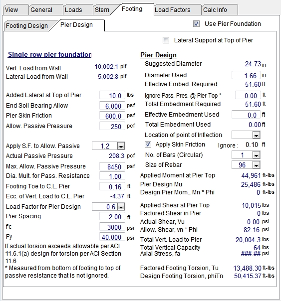
This allows you to use drilled cast-in-place concrete piers spaced in a single row along the length of the wall. The default is without lateral support at the footing level. If lateral support is available, such as an abutting slab at the footing level, check the box labeled "Lateral support at Top of Pier". The Key Dimensions & Sliding tab is not applicable when piers are used so the Key Dimensions & Sliding Options tab is not displayed when the Use Pier Foundation checkbox is checked. However, the Footing Design tab does remain active, so you can adjust the footing dimensions as necessary for the piers, and adjust as needed for torsion resistance (see below).
| Lateral Support at Top of Pier: | Provides a way to specify that there is lateral restraint at or near the top of the pier. If this option is checked, the program will offer a related item named "Assumed Fixity Below Embed" |
| Vert. Load from Wall, plf: | Displays the total vertical load imposed upon the piers from the wall above, including the footing weight. It matches the total vertical load from the Resisting Moment summary. |
| Lateral Load from Wall, plf: | Displays the net sliding force and matches the total force shown on the Overturning Moments summary for the wall. |
| Added Lateral at Top of Pier, lbs: | The geotechnical engineer may recommend an added lateral force at or near the top of the pier (sometimes termed “creep”). This may be a triangular force but for simplicity it is assumed to act at the top of the pier. |
| End Soil Bearing Allow, psf: | Allowable end bearing pressure at bottom of pier. |
| Pier Skin Friction, psf: | If applicable, enter the allowable skin friction on the pier for added vertical load capacity. This may require conversion from a friction angle. |
| Allow. Passive Pressure, pcf: | This is used to define the variation in allowable passive pressure with depth. |
Apply Safety Factor to Allowable Passive Pressure: Allows the user to use a drop-down list box to select a safety factor that will be applied to the calculated passive pressure
| Actual Passive Pressure, pcf: | Reports the value of Allowable Passive Pressure in pcf divided by the safety factor selected above. |
| Max. Allow. Passive Pressure, psf: | Specifies the upper limit on the allowable passive pressure. The allowable passive pressure will increase with depth until it reaches this value, at which point the allowable passive pressure will remain constant at this value. |
| Diameter Multiplier for Pass. Resistance: | The geotechnical engineer may permit a multiplier to the diameter for greater effective passive resistance. The default is 1.0. |
| Diameter Required, in: | Diameter required based upon applied Vertical Load and the allowable end soil bearing pressure. |
| Diameter Used, in: | If skin friction is used (activated by checkbox below) the diameter can be adjusted provided Total Bearing Capacity exceeds Total Vert. Load to Pier. |
| Effective Embedment Required, ft: | This uses the “pole embedment” equations per IBC ’06 Section 1805.7.2 or IBC '09 Section 1807.3 or IBC '12 Section 1807.3 to determine the required pier embedment depth based upon the passive pressure entered and the applied moment to pier. The embedment depth will vary depending upon whether the checkbox for lateral support at top is checked. |
| Ignore Passive Pressure from Pier Top, ft: | Since the soil near the top of a drilled pier may be disturbed and uncompacted, it may have little or no passive resistance. This entry gives the option to neglect the passive pressure over the specified height at the top of the drilled pier. |
| Total Embedment Required, ft: | Displays the sum of "Effective Embedment Required" plus "Ignore Passive Pressure from Pier Top". |
| Effective Embedment Used, ft: | Input a depth of embedment considered to be effective below the section where passive pressure is being ignored. |
| Total Embedment Used, ft: | Displays the sum of "Effective Embedment Used" plus "Ignore Passive Pressure from Pier Top". |
| Location of point of inflection: | Use the drop-down list box to select the ratio of depth-to-inflection to effective embedment depth. Tests suggest 1/6 is reasonable; 1/3 is conservative. This will be used to calculate the maximum moment applied to pier. The resulting length will be measured below the zone where passive pressure is ignored (if any). |
Apply Skin Friction (with option to ignore some length of skin friction): Check this if skin friction is to be used to increase vertical capacity of pier. If selected, there is an entry for depth to be ignored for skin friction.
| No. of Bars (circular): | Select the number of bars. They are assumed to be in a circular pattern. |
| Size of Rebar: | Select size of bars to use in the circular pattern. |
| Applied Moment at Pier Top, ft-lbs: | Displays the wall overturning moment multiplied by the pier spacing. |
| Pier Design Mu, ft-lbs: | This is the total factored design moment applied to the pier. |
| Allow. Pier Mom., phi Mn, ft-lbs: | Displays the design moment capacity of the pier using the strength values input and a phi factor of 0.90. This uses the Whitney Approximation method which is slightly conservative. |
| Applied Shear at Pier Top, lbs: | Displays the Lateral Load from Wall multiplied by the pier spacing. |
| Shear in Pier, lbs: | Displays the total factored design shear applied to the pier. It includes lateral load from the wall, and additional shear due to the pier reacting out the applied moment. |
| Actual Shear, Vu, psi: | Displays factored shear stress determined using Whitney Equivalent Rectangular Section. |
| Width = b = 0.8 * Diam. |
| Area of Whitney Equivalent Rectangular Section = Area of circular pier |
| H = Area / b |
| d = 0.67 * H |
| Aeff = b * d |
| Allow. Shear, phi Vn, psi: | Displays design shear strength using a phi value of 0.75: phi vn = 0.75*2*(fc)1/2 |
| Total Vert. Load to Pier, lbs: | Displays the Vertical Load from Wall multiplied by the pier spacing. |
| Total Vertical Capacity, lbs: | This combines both end bearing capacity and skin friction, as applicable. |
| Axial Stress, fa, psi: | This is the total vertical load / pier area. This is for reference only since it is not considered a critical design consideration. |
| Footing Torsion, Tu, ft-lbs: | Displays factored torsional force in footing, which is calculated as moment from wall multiplied by one-half pier spacing. |
Footing Torsion Allow., phi Tn, ft-lbs: Displays torsional design strength of the footing based on ACI 318-05 Section 11.6.1 or ACI 318-08 Section 11.5.1 or ACI 318-11 Section 11.5.1.
| DESIGN STATUS messages: | If “Pier Problem” is displayed, vertical load capacity or moment capacity is exceeded, or embedment depth is insufficient. |
For more information on pier foundation design see Basics of Retaining Wall Design, 9th Edition