Stem Tab for Gravity Retaining Wall |

|

|
Stem Tab for Gravity Retaining Wall |
|
|
Stem Tab for Gravity Retaining Wall
When a Gravity Retaining Wall is defined, the Stem tab will appear as shown below:
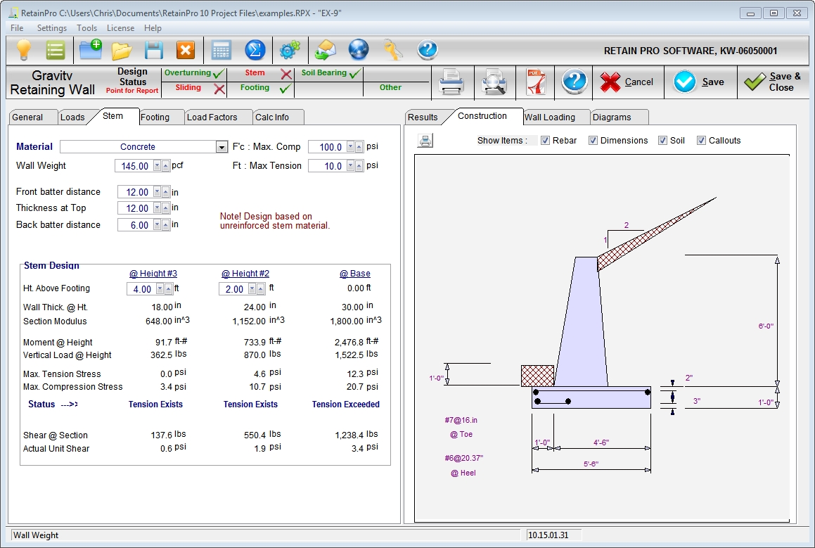
Gravity walls may have one or both sides tapered and are assumed to be proportioned such that no reinforcing is required since every section is primarily in compression. Any solid homogeneous material may be used. Reinforcing can be added if there is any tension in the cross section, but the program does not compute this requirement.
| Material: | Use this drop-down list box to specify the material being considered. |
| Wall Weight: | Enter the weight of the wall material in pcf. Generally this will be the weight of concrete or rubble (approximately 145 pcf). |
| Front Batter Distance: | Enter the offset of the front face at top of the wall from the front face at the base. |
| Thickness at Top: | Enter the thickness of the top of the wall. |
| Back Batter Distance: | Enter the offset of the back face at the top of the wall from the back face at the base. |
| F’c Max. Compression: | Enter your criteria for the maximum permissible compressive stress on the wall. Usually varies from 100 psi to over 700 psi. |
| Ft Max. Tension: | Enter your criteria for the maximum permissible tensile stress on the wall. Usually varies from about 15 psi to 40 psi. Generally gravity walls are designed such that there is no tension – the full cross section is in compression. |
Stem Design
Stem design will automatically be performed at the bottom of the stem (interface with the footing). In addition, you can specify two additional heights above the base to check stresses. These are identified as "@ Height #2" and "@ Height #1", where the latter is the lower height.
| Height Above Footing: | Specify two heights above the top of footing elevation where stem stresses should be checked. Height #2 is highest and @Stem Base will be fixed at 0.00. |
| Wall Thickness @ Height: | Displays the calculated values of wall thickness at the heights you have specified for analysis. |
| Section Modulus: | Displays the computed section modulus at the heights selected for analysis. |
| Moment @ Height: | Displays the moment at the designated design heights. |
| Vertical Load @ Height: | Displays the summation of vertical loads above designated height. |
| Maximum Tension / Compression Stress: | Displays extreme tension and compression stresses based on interaction formulas. |
| Status: | Indicates "OK" if not tension exists. If tension exists but it does not exceed the user-specified threshold then the status indicates "Tension Exists". If tension exists to a degree that exceeds the user-specified threshold then the status indicates "Tension Exceeded". If compression exists to a degree that exceeds the user-specified threshold then the status indicates "Compression Exceeded". |
| Shear @ Section: | Displays total shear force at the designated height. |
| Actual Unit Shear: | Displays the calculated shear stress at the designated height. Compare this with the allowable shear for the material you have selected. |