Stem Tab for Restrained Retaining Wall |

|

|
Stem Tab for Restrained Retaining Wall |
|
|
Stem Tab for Restrained Retaining Wall
When a Restrained Retaining Wall is defined, the Stem tab will appear as shown below:
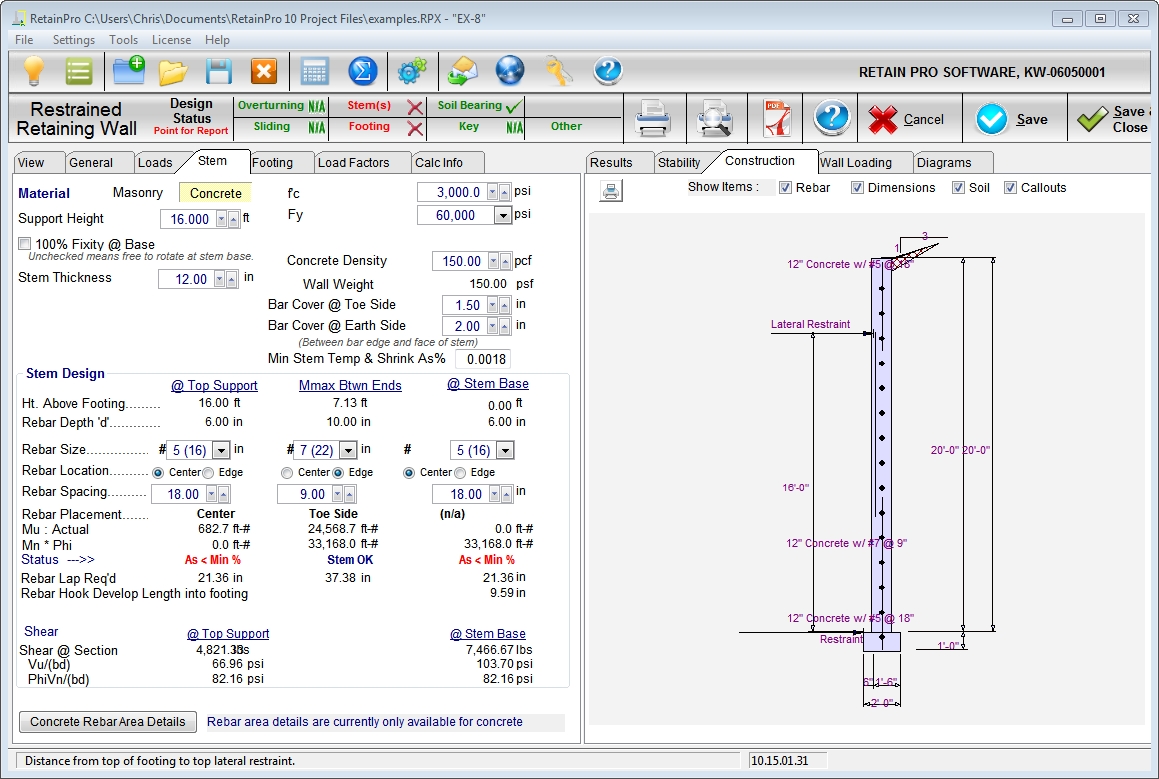
If Restrained Stem is selected, you may have a lateral support (such as an abutting roof, slab-on-grade over backfill, or tiebacks). The lateral support should be near the top of the wall, although some extension of the wall above the support is permitted by the program. You have the option of fixing the base (as for a cantilevered wall) or assuming it pinned. Intermediate degrees of fixity are not permitted. The program will compute moments, shears, and stresses at three locations: base (negative moment if fixed; zero moment if pinned), maximum positive moment between base and lateral support, and at the point of lateral support.
| Material: | Select Masonry or Concrete. Only one material can be used, and must be of constant thickness. |
| Support Height: | Use the spinners to define the height from base to the elevation of the lateral support. |
| 100% Fixity @ Base: | Clicking this box will model the stem as being fully fixed at the base (connection to the footing). If unchecked, the stem will be considered pinned to the footing (no moment fixity). |
| Stem Thickness: | The program only permits a constant thickness throughout the height of the wall. Use the spinners to establish the stem thickness. If Masonry is chosen, the drop-down list box will offer common CMU sizes. |
| Design Method: | (Only applies to Masonry stems) Select the design method to be used, either ASD or LRFD. |
| Multiply Block Weight By: | (Only applies to Masonry stems) Provides a multiplier input field in case it becomes necessary to adjust the data. See Appendix C for masonry wall weights. |
| Solid Grout: | (Only applies to Masonry stems) If this box is checked the weight of the wall will be based upon industry standard values for the weights of solid-grouted walls of lightweight, medium weight, or normal weight block based on the selection for CMU weight type. If this box is not checked, the program will calculate the weight based upon grouting of only cells containing reinforcing. This also affects equivalent solid thickness for stem shear calculations, and area for axial stress calculations (combined with moment for masonry stems). |
| f'm: | For Masonry stem segments, enter the compressive strength of masonry in units of psi. This input is not applicable to Concrete stem segments. |
| f'c: | For Concrete stem segments, enter the compressive strength of concrete in units of psi. This input is not applicable to Masonry stem segments. |
| Fs: | For ASD masonry design, select the allowable steel stress, based on working stress design, which should be used for design of the masonry stem segment. The drop-down list box allows quick selection of common values. This input is not applicable to LRFD masonry design or to concrete design. |
| Fy: | For LRFD masonry design and for concrete design, select the rebar yield stress to used for design of the indicated stem segment. The drop-down list box allows quick selection of common values. This input is not applicable to ASD masonry design. |
| Em = f'm *: | This input collects the value by which the compressive strength of masonry is multiplied to arrive at the value of the modulus of elasticity for masonry. IBC ’06 specifies Em = 900*f’m which is the default value. |
| CMU Type: | (Applies to Masonry stem segments only.) This input provides a drop-down list box that offers the common CMU weights. |
| Concrete Density: | (Applies to Concrete stems only.) This input provides spinners to define the unit weight of the concrete for the stem. |
| Rebar Cover: | This appears if a concrete stem is chosen and lets you enter desired cover on toe and earth side. The cover is used to calculate the "d" dimension when the rebar is specified to be in the "Edge" position of Concrete stems in the Stem Design category, which is explained in more detail below. When the rebar is specified to be in the "Edge" position of Masonry stems, the program uses tabular data on the geometry of various CMU sizes to calculate the "d" dimension. (Refer to the "Stem Tab for Cantilevered Retaining Wall" topic for detailed information regarding the calculated "d" dimension for Masonry stems.) |
Stem Design
This allows you to design or check wall moment and shear at three locations: @ Top Support, @ Mmax Between Ends, and @ Stem Base. If base is pinned, the entries under @ Stem Base will be zero or dimmed.
| Ht. Above Footing: | This displays, from left to right, the distance from the top of footing up to the lateral support, the distance from the top of footing up to the point of maximum positive moment, and it displays 0.00 ft to represent the design that is performed at the base of the stem. |
| Rebar Depth "d": | From the thickness and center/edge condition, the program determines the "d" dimension to be used for design (using internal tables and default modifications). See Rebar Position above. For concrete stems with bars in the "Edge" position, the program automatically uses the specified clear cover and assumes a one-half inch allowance for one-half of a bar diameter when determining "d". |
| Rebar Size: | Select from the drop-down list box. |
| Rebar Location: | Choose Center or Edge placement. |
| Rebar Spacing: | For Concrete stems, use the spinners to increment the rebar spacing. For Masonry stems, use the drop-down list box to select a modular spacing. |
| Rebar Placement: | Serves as a convenient reminder to indicate which side of the wall the specified rebar is considered to be placed on. |
| Mu: | (Only for Concrete Stems and for Masonry Stems designed according to LRFD) Displays factored moments at the indicated locations with (+) and (-) as applicable. For concrete stems and for masonry stems designed according to LRFD, the moments will be factored by the load factors specified on the Load Factors tab. |
| Actual Moment: | (Only for Masonry Stems designed according to ASD) Displays actual moments at the indicated locations with (+) and (-) as applicable. |
| ϕMn: | (Only for Concrete Stems and for Masonry Stems designed according to LRFD) This is the design moment strength, which will be based upon the bar sizes and spacings you established, along with wall geometry, concrete strength, etc. |
| Allowable Moment: | (Only for Masonry Stems designed according to ASD) This is the allowable moment capacity based upon the bar sizes and spacings you established, along with wall geometry, concrete strength, etc. |
| Status: | This indicates whether the stem design is OK at the specified height. If there is a problem, this will display a descriptive message such as "Mu > Phi * Mn" or "As < min" or "As > max" or "Ftg. Rebar Embed!". |
| Rebar Lap Req'd: | For masonry, the lap required is 48 bar diameters for Fs = 32,000 psi and 40 diameters for Fs = 20,000 psi. For concrete, a Class B splice is assumed, which multiplies the development length by 1.3 (See ACI 12.15.2), and excludes reduction for stress level. Note: The program does not compute or display bar cut-off points, which must be done manually, or extend positive reinforcing so it is acceptable. |
Rebar Hook Development Length into Footing: This is the hooked development length that is required for the bar size specified at the stem base. It is based on the assumption that the bar is hooked into the footing with a 90° bend and minimum 12 db bar extension. The calculated values is also based on the assumption that the side cover (normal to the plane of the hook) is not less than 2.5 inches and that the cover on the extension beyond the hook is not less than 2 inches. These latter assumptions facilitate the application of a factor of 0.7 to the calculated value of ldh.
| Shear at Section: | This is the total shear force at the indicated height (factored for concrete or masonry designed according to LRFD). |
| Factored Shear Stress: | (or Applied Shear Stress for Masonry Stems designed according to ASD) Shear stress at designated height computed by Shear at Section / (12 * "d") (factored for concrete or masonry designed according to LRFD). |
| Design Shear Strength: | (or Allowable Shear Stress for Masonry Stems designed according to ASD) For masonry designed by ASD according to TMS 402/ACI 530, the allowable shear stress varies between 3*sqrt(f'm) and 2*sqrt(f'm) as a function of M/(Vd). No contribution of shear strength is assumed from reinforcing steel in a retaining wall. |
For masonry designed by LRFD according to TMS 402/ACI 530, the nominal shear strength varies between 6*Anv*sqrt(f'm) and 4*Anv*sqrt(f'm) as a function of M/(Vd). Again, no contribution of shear strength is assumed from reinforcing steel in a retaining wall.
For concrete, the nominal shear strength is 2*λ*sqrt(f'c), per ACI 318.